2

Recently I needed to reverse engineer a simple populated-PCB. I have read this article.

My process is simple:

  1. Photograph the underside of the PCB.
  2. Edit it in GIMP and draw lines over the tracks.
  3. Save the layer as a png.
  4. Run 'autotrace' and generate a SVG file.
  5. Edit the SVG and insert component symbols and hook them up to the traces.

I'm having trouble with the last step in Linux. I tried using 'Dia' as suggested but the tool sucks (you can't connect components easily to the trace-lines, and you can't draw straight lines easily, you can't rotate components in my version, and you can't scale the entire diagram - you can zoom).

Is there some tool that one can use to edit a SVG file which has the traces already inserted, and just draw straight lines and insert circuit symbols and hook everything up quickly? I don't mind if it's a windows only tool.

2
  • Been a while since I've used it but Microsoft Visio has a 60 day trial and can work with SVG files so might be worth a try. Personally though once I'd worked out the track connections because it's a simple circuit I'd redraw in something like Eagle and the final schematic will look a lot neater than something that tries to follow the track layout.
    – PeterJ
    Commented May 31, 2014 at 3:57
  • You might want to look into using some sort of dedicated circuit design and simulation software. I don't know much about them, but I remembered coming across one a while back. This article from Make might be a good starting point: makezine.com/2009/11/15/ask-make-3
    – Notre1
    Commented May 31, 2014 at 13:42

2 Answers 2

3

You can use EAGLE Freeware. Freeware got some limitations like:

  • The usable board area is limited to 100 x 80 mm (4 x 3.2 inches).
  • Only two signal layers can be used (Top and Bottom).
  • The schematic editor can only create one sheet.
  • Support is only available via email or through our forum (no fax or phone support).
  • Use is limited to non-profit applications or evaluation purposes.

Some features of its schematic editor are:

  • Automatic generation of contact cross references
  • Simple copying of parts
  • Replace function for parts without loss of consistency between schematic and layout
  • Online Forward&Back Annotation between schematic and board
  • Automatic generation of supply connections
  • Automatic board generation
  • Electrical Rule Check (error check in the Schematic and consistency check between Schematic and Layout)
  • User Defined Net Classes for Via Size, Wire Width and Clearance


I used EAGLE and Labcenter Electronics - Proteus around a year ago. Unfortunately Proteus is Windows only. I don't know if you can run it through WINE and it's not free. I felt it was easier in Proteus than EAGLE. But in this 12 months many things must have been changed.

2

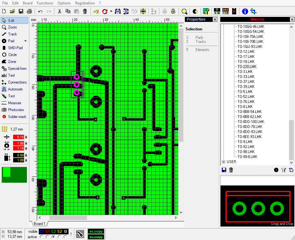
Have a look at Abacom Sprint Layout:

  • Windows software; runs on Wine too
  • not free
  • allows you to overlay a photo of the PCB and draw over it (Extras - Scanned Copy)
  • demo version available

enter image description here

2
  • neat tool! i was able to draw the tracks and pads in no time, BUT now what? how do I flip and populate, then rearrange the wiring into something resembling a ckt
    – user3443
    Commented May 31, 2014 at 10:01
  • It's under: Extras-Scanned Copy, also you need to set 'Measure in the panel to the left, and select an appropriate grid spacing for the 'Pad' and 'Track to work since they center on grid-nodes.
    – user3443
    Commented May 31, 2014 at 10:54

Your Answer

By clicking “Post Your Answer”, you agree to our terms of service and acknowledge you have read our privacy policy.